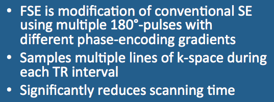
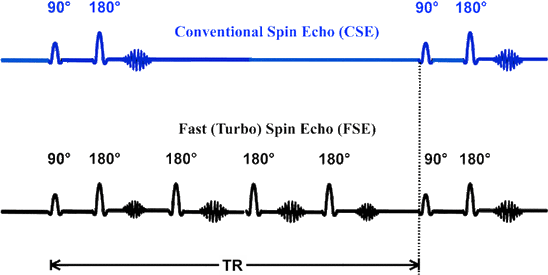
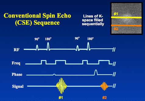
- CSE: 90º−180º−echo………………………………………………………90º−180º−echo……
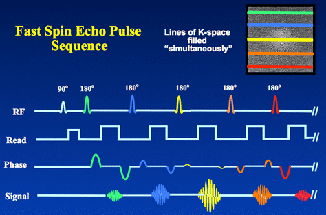
- FSE: 90º−180º−echo−180º−echo−180º−echo−180º−echo……………90º−180º−echo……
|
The FSE/TSE technique, however, changes the phase-encoding gradient for each of these echoes (a conventional multi-echo sequence collects all echoes in a train with the same phase encoding). As a result of changing the phase-encoding gradient between echoes, multiple lines of k-space (i.e., phase-encoding steps) can be acquired within a given repetition time (TR).
Because of multiple phase-encoding lines are acquired during each TR interval, FSE/TSE techniques may significantly reduce imaging time. |
When the number of slices is not the limiting factor, imaging time is inversely proportional to ETL. That is, an FSE/TSE sequence with an ETL=8 can be performed in one-eighth the time of a conventional SE sequence with the same TR.
Reduction of magnetic susceptibility artifacts may be disadvantageous, however, as FSE images are less likely to detect small areas of calcification or hemorrhage. Other limitations of FSE include overly bright signals from fat on T2-weighted images and overly bright CSF on spin-density-weighted images. Increased tissue heating secondary to multiple 180°-pulses may also limit FSE use in infants and and small children.
Advanced Discussion (show/hide)»
Additional Notes on the FSE/TSE Sequence
Although the pulse diagram above and later discussion are focused on a Cartesian/rectilinear trajectory, FSE/TSE can be used with virtually all k-space sampling strategies, including spiral, radial, circular, and PROPELLER methods.
FSE/TSE can be used in either 2D or 3D mode. In 2D acquisition, multiple slices are nearly always interleaved because the TR is generally longer than the sequence length. The time savings afforded by the FSE/TSE technique has made 3D acquisition realistically possible for the first time.
In the FSE/TSE pulse sequence diagram above you will note that each positive phase encode gradient is paired with a negative gradient immediately after the echo. This rewinds the phase at each step allowing each line of k-space to be traversed in the same direction.
The refocusing pulses need not be exactly 180° . To reduce energy deposition (specific absorption rate/SAR) in tissues, smaller flip angles (e.g. 130-160°) may be used. This creates some interesting phenomena known as "hyperechoes", described in a later Q&A.
Regardless of the flip angle used for refocusing pulses, the signals for FSE/TSE sequences include both primary spin echoes from the closest pair of RF-pulses and stimulated echoes resulting from the combined effects of multiple prior RF-pulses.
The distribution of specific phase-encoding values to echoes in the train determines image contrast and influences artifacts. Usually it is preferable to gently change the phase steps between echoes in a stair-step pattern, thus reducing artifacts from k-space discontinuities. Different manufacturers approach this problem differently. See, for example, Hitachi's "Prime FSE" strategy in the references below.
Hennig J, Nauerth A, Friedburg H. RARE imaging - a fast imaging method for clinical MR. Magn Reson Med 1986; 3: 823-833.
Hitata Y, Sasaki M, Esashika K, Gakumazawa H. Hitachi's Prime Fast Spin Echo technology: efficacies in improving image quality and usability. (Sales brochure for Hitachi's version of FSE, giving some insight into how various manufacturers have different approaches to echo ordering and data collection in what is essentially the same basic sequence).
Walker MT, Partovi S, Karis JP, Fram EK. Fast, versatile, and cost-effective FSE MR imaging: technical considerations and clinical applications. Barrow Quarterly 2000;16:1-5.
Zur Y. Analysis of the multi-echo spin-echo pulse sequence. Concepts Magn Reson Part A 2017;46A:321302. [DOI LINK]
How do you select parameters for fast spin echo imaging? There are several new ones to set.


