|
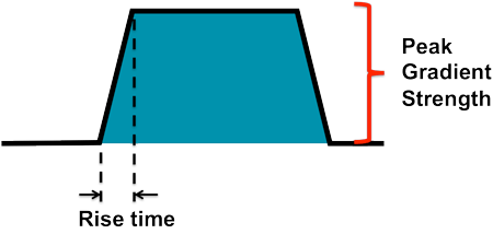
Both spatial resolution and imaging speed depend upon good gradient performance, and scanners do differ in their gradient specifications. Electrical currents are pulsed on and off during imaging, and gradients typically have a trapezoidal waveform as shown in the diagram to the left from which various measurements are derived.
|
Rise time is measured in milliseconds, and is typically in the range of 0.1-0.3 msec for most scanners. Rise time is meaningless by itself, because a scanner with very weak gradients might ramp up to full strength very quickly, but have overall poor gradient performance for imaging. What is important is not the absolute value of rise time, but rise time scaled according to the maximum achievable gradient strength. This is encapsulated in the slew rate, defined as
The slew rate influences the minimum attainable TR and TE for conventional MR imaging and influences the echo spacing in fast spin echo and echo planar applications. In the current marketplace, high field superconducting scanners boast slew rates in the 150-200 T/m/s range; superconducting open scanners in the 100-120 T/m/s range; and lower field permanent scanners on the order of 50 T/m/s.
The need for strong gradients and high slew rates depends on your intended scanner use. If cardiac or brain imaging is anticipated, then powerful gradients are mandatory. If the intended scanner use is for orthopedics, however, such demanding gradients may not be required.
Caveat emptor: The typical gradient strengths and slew rates quoted above are per axis (i.e. values for the x-, y- and z-gradients individually). Some vendors, often those with somewhat inferior gradient performance, will instead quote effective gradient strengths and slew rates. Because three gradients are averaged together, the effective gradient strength and slew rates are 1.73 (=√3) times larger than the per axis values.
Advanced Discussion (show/hide)»
Even larger gradient strengths and slew rates may be obtained in special situations. GE Healthcare's Optima 430s 1.5T extremity scanner (formerly sold by ONI) boasts 70 mT/m gradients at slew rates of 300T/m/s. Insertable gradients are used in many research centers, especially for neuroimaging, where a separate set of gradients is placed within the scanner bore close to the patient. Because of the small size of these systems, very high gradient performance parameters may be obtained.
Duty Cycle Definitions
The term “duty cycle” can be defined in several ways and it is not always clear which definition is being used in a given situation. The first definition is what percentage of time a gradient may oscillate between maximum positive and negative values without overheating. The second definition is the percentage of time gradients may be run at maximum strength without switching. The third definition is the root mean squared (RMS) gradient power divided the the square of the maximum gradient strength. This latter definition is most highly dependent on the pulse sequence used as well as the gradient subsystem itself
Hidalgo-Tabon SS. Theory of gradient coil design methods for magnetic resonance imaging. Concepts Mag Res Part A 2001; 36A:223-242.
What are gradient coils?

